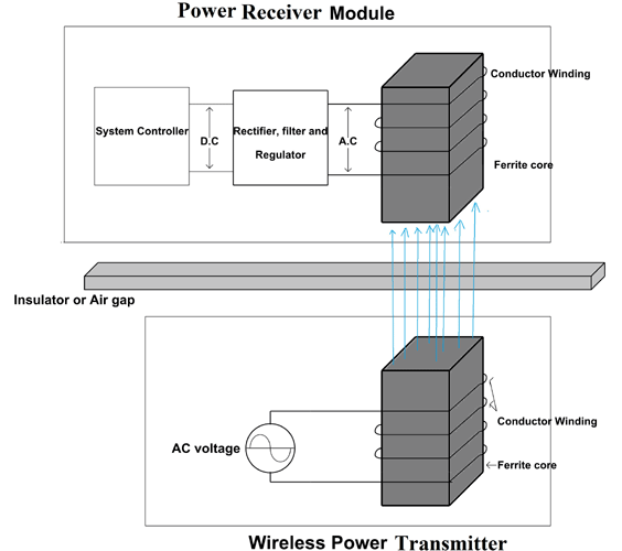
Take two lengths of copper wire and coil them the coiling helps amplify the magnetic fields well be generating. Energy transfer by electromagnetic induction to the receiver via inductive coupling.
Resonant Inductive Coupling As A Potential Means For
Wireless Power Transfer Through Inductive Coupling

Wireless Power Transfer Wikipedia
Attach one length of copper wire to a battery.

Inductive coupling experiment. Principle of wireless power transfer using inductive coupling. A current mode driver generates a differential signal. An inductively coupled transponder consists of a solid state transceiver chip connected to a large coil that functions as an antenna.
Unintentional inductive coupling can cause signals from one circuit to be induced into a nearby circuit this is called cross talk and is a form of electromagnetic interference. As seen in the figure 7 the coil provides the inductance. It is simply the inducer coil glued to a note card wrapped in electrical tape.
Experimental setup has been studied to get the performance of wpt. The capacitor is connected in parallel to the coil. Thank you for viewing i hope you enjoy this as much as i have.
Alternatively inductive coupling does not require as small a separation of the planes as in the capacitive coupling technique relaxing the demand for very thin spacing between planes. And dont forget to vote this as you favorite and share it with your friends. To learn more about the physics behind magnetic inductive coupling and wireless power.
In this experiment a mobile phone devices is used as an load. Resonance inductive coupling inductance induces current in the circuit. Its easy to see the effects of inductive coupling with a simple experiment.
You now have a very simple circuit as electrons flow from one end of the battery through the wire and into the other end of the battery. A basic analysis of inductive coils and its parameter calculations are presented. Mutual inductance is the basic operating principal of the transformer motors generators and any other electrical component that interacts with another magnetic field.
The experimental setup of transceiver unit has been conducted. Energy will be shifting back and forth between magnetic field surrounding the coil and electric field around the capacitor. Three different lab scale coil models such as square circular and rectangular coils are wounded to evaluate the magnetic field by experiment to validate the.
Then we can define mutual induction as the current flowing in one coil that induces a voltage in an adjacent coil. The receiver amplifies the transmitted current or voltage pulses producing a full swing signal. A resonant transformer of this type is often used in analog circuitry as a bandpass filter.
Resonant inductive coupling or magnetic phase synchronous coupling is a phenomenon with inductive coupling where the coupling becomes stronger when the secondary load bearing side of the loosely coupled coil resonates. The simulations of mutual inductance coupling factor calculations are demonstrated with graphical analysis.

Wireless Power Transfer Via Inductive Resonant Coupling

Practical Exercises For Learning To Construct Nmr Mri Probe

Mutual Inductance Of Two Adjacent Inductive Coils
Wireless Power Transmission Using Resonance Inductive Coupling

Crosstalk Reduction Between Pcb Traces In Compliance Magazine

Wireless Power Transfer Wikipedia

Inductive Coupling An Overview Sciencedirect Topics

Guard Trace Impact On Crosstalk Between Pcb Traces In

Basic Tesla S Experiments Part 2 Capacitive Coupling

Different Types Of Wireless Power Transfer Technologies And

Another Inductive Coupling System For Rotary Beams

File Resonant Inductive Coupling Experiment Conducted By
Comments
Post a Comment